 Luca
dfd8f1d9e3
Luca
dfd8f1d9e3
Overview of the day's work aimed at a general reader: what the EPS unit
needs, how the two-adapter bench was wired around the cut CAN bus, the
steps from transparent relay to standalone control, and the four
misleading failures along the way (frozen alive counters, transmit rate
starvation, local command dispatch, and CAN needing a second node to ACK).

Also acts as an index into the existing documentation, and pins the
direct Python dependencies the app needs.
9.7 KiB
Running a BMW electric power steering rack outside its car
A day of reverse engineering: taking the electric power steering (EPS) unit from a 2010 BMW 1-series and working out exactly what it needs to be told in order to work on a bench — and eventually in a custom EV.
The short version
A modern power steering rack isn't a dumb hydraulic pump you can just bolt in and give 12V. It's a computer. It sits on the car's CAN bus listening to dozens of other computers, and it refuses to do anything until it's satisfied that it's installed in a real, running car.
The question was: what does it actually need to hear?
The answer turned out to be far less than expected:
Two CAN messages and one 12V wire.
0x130— the ignition/terminal status, sent 10 times a second0x1A0— the road speed, sent 50 times a secondThat's 60 messages a second. The car itself puts about 1,330 a second on that wire — so more than 95% of the traffic turned out to be irrelevant to steering.
Road speed is the interesting one: it's what tells the rack how much assist to give. Slow speed means lots of assist for parking; high speed means less, so the steering firms up on the motorway. Feed it a speed value and you control the assist directly.
The setup
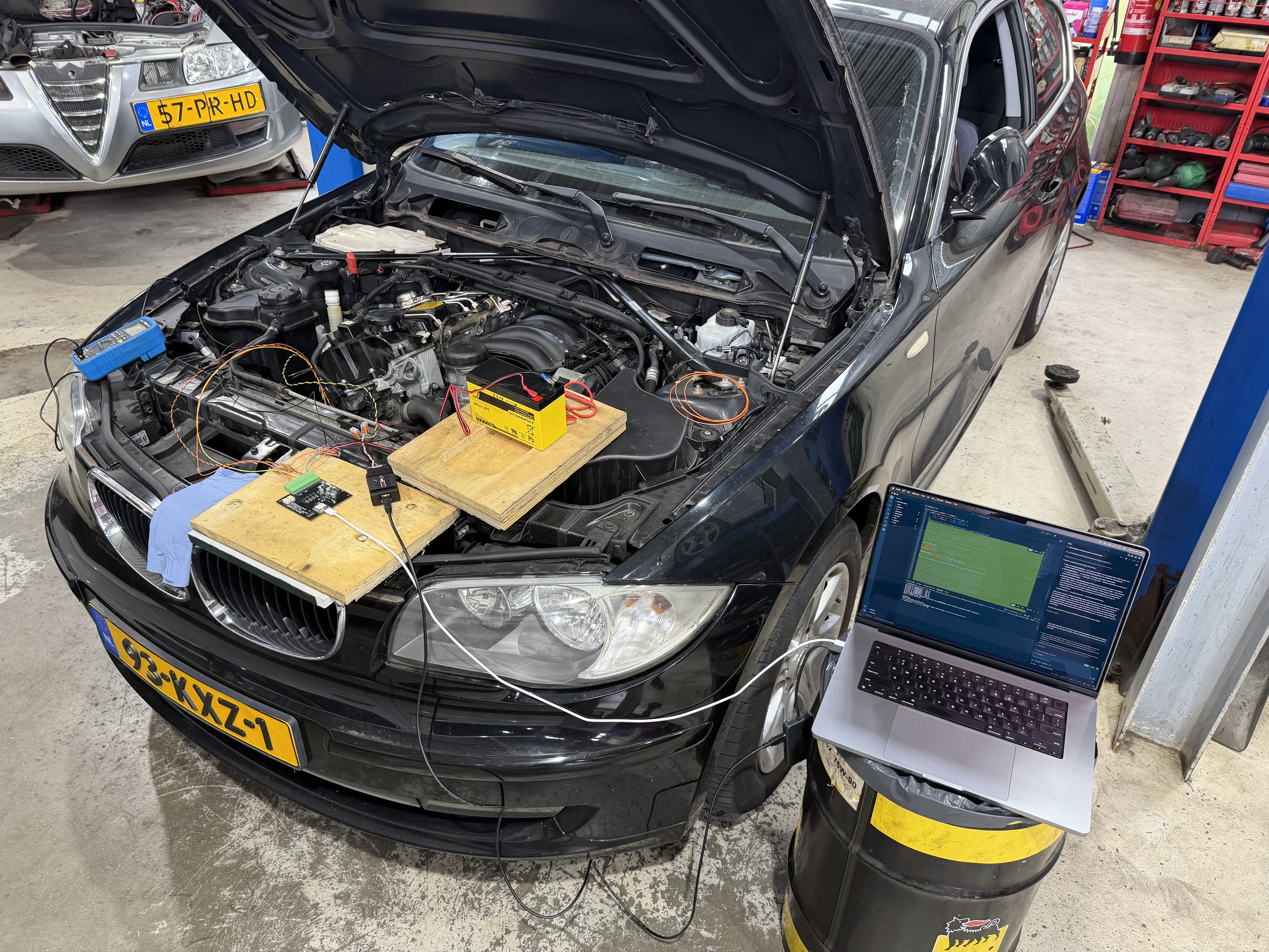
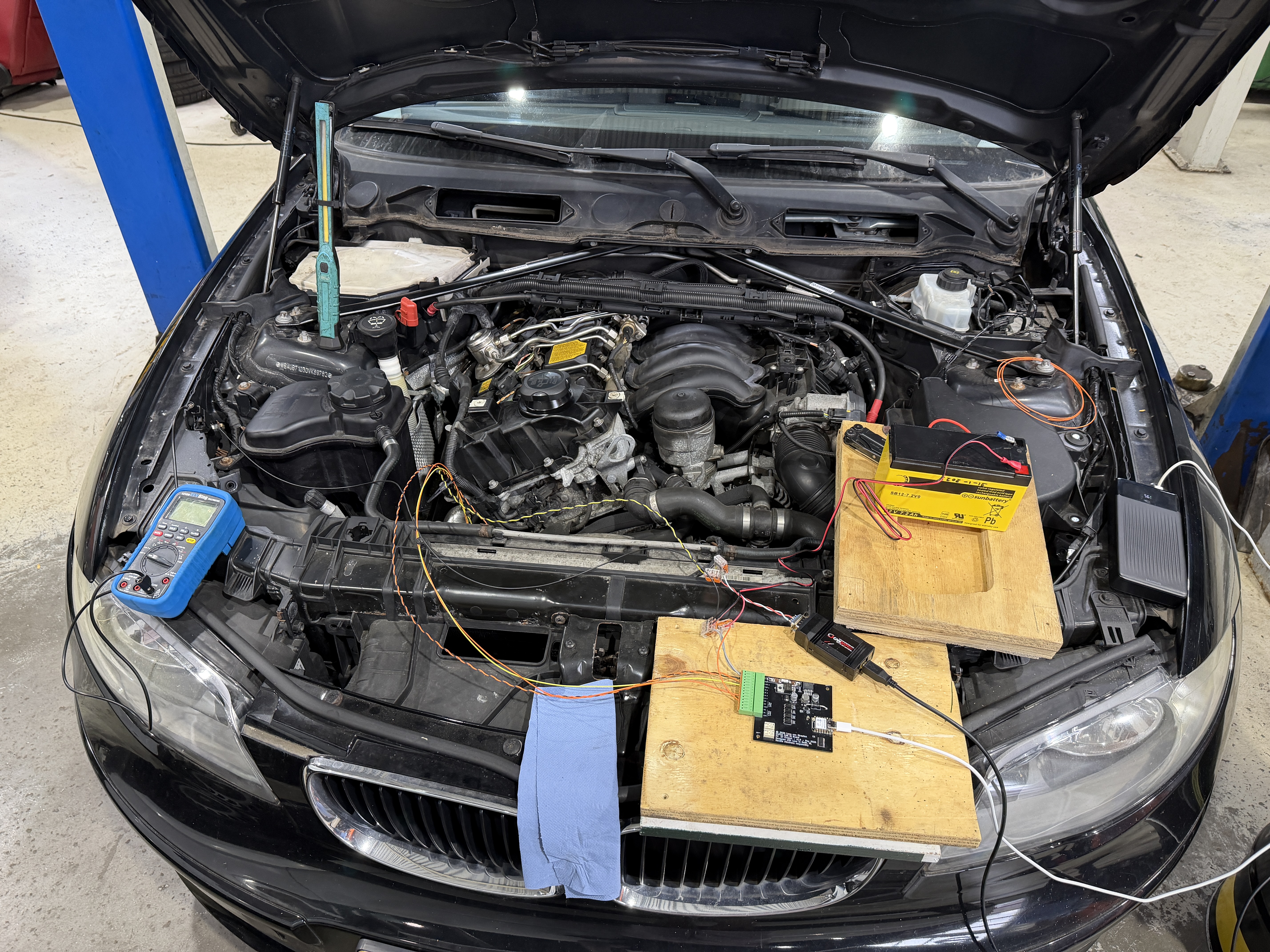
The donor car and the steering rack were both kept intact — the only change was cutting the CAN bus wire between the car and the EPS unit, and inserting a laptop in the gap.
   ┌─────────┐        ┌──────────────┐        ┌─────────┐
   │   CAR   │◄──────►│    LAPTOP    │◄──────►│   EPS   │
   │ PT-CAN  │        │   (gateway)  │        │  rack   │
   └─────────┘        └──────────────┘        └─────────┘
     adapter 1                                  adapter 2
                              │
                              └── 12V enable signal (a plain wire, not CAN)
Two CAN adapters, one on each side of the cut:
- Adapter 1 — the car side. A commercial USB-CAN adapter (a CANdapter) listening to the car's powertrain bus.
- Adapter 2 — the EPS side. A small custom board (Seeed XIAO ESP32-S3) that does double duty: it's a USB-CAN adapter and it has relay outputs and opto-isolated inputs, which turned out to be essential.
That second board mattered because of something easy to miss: the EPS doesn't wake up from CAN alone. The car also sends it a separate 12V enable signal on an ordinary wire. Without that, the unit is completely dead — no CAN, no assist, nothing. So the board reads that 12V signal coming from the car on an input, and can reproduce it to the EPS on a relay output. That let us take over the enable line and switch the rack on and off ourselves.
How it went — the steps
1. Talk to the adapters at all
Started from nothing: which USB device is this, what protocol does it speak? It identified as an FTDI serial chip, and turned out to be a CANdapter speaking a variant of the standard SLCAN protocol — close enough to look standard, different enough that the off-the-shelf library silently mangled every frame. Wrote a small driver for it instead.
2. Find the bus speed
Scanned the common automotive bitrates. The first attempt found nothing at any speed — which was actually informative, because a wrong bitrate and a wrong wiring look different in the data. CAN H and L had been swapped. Once corrected: 500 kbit/s, clean traffic.
3. Watch the car and understand it
Recorded the car starting and stopping, then decoded the bus: engine speed, steering angle, road speed, ignition state, wheel speeds. Built a live dashboard to see it all moving in real time. Roughly 70 different message types on that one wire.
4. Sit in the middle — the transparent relay
With the bus cut and the laptop bridging it, everything was forwarded in both directions. If done right, the car shouldn't notice. It worked — the steering assisted normally with a laptop in the middle of the loop.
5. Start taking things away
This is where the real answer comes from: block messages one at a time and see if the rack still works. Turn off the VIN broadcast, the radio buttons, the diagnostics — does steering still assist? Keep cutting until something breaks.
6. Cut the car out entirely
Replay a recording of the car to the rack, with no car connected at all. Then narrow the recording down. Then stop replaying and generate the messages from scratch. Each step is a stronger claim: from "we can copy the car" to "we understand the car well enough to be the car".
7. Take control
The end result is a control panel: a button to bring the rack up, a button to shut it down, and a slider for road speed that changes how much assist it gives — with no car involved anywhere.
Things that went wrong (and what they taught us)
The interesting part of a day like this is rarely the plan working. Four problems, each of which looked like a hardware fault and wasn't:
"The rack won't wake up." We were replaying recorded messages perfectly — byte for byte. Too perfectly. Each message carries a small counter that ticks up every time it's sent, and replaying a frozen snapshot meant that counter never moved. Every other computer on the bus reads a stuck counter as "this sender has crashed" and ignores it. Fixed by cycling through the real recorded sequence so the counters advance naturally.
"It works, then randomly drops out." The laptop was only managing about 264 messages a second against the ~1,330 needed — five times too slow, so everything arrived late. To the rack, chronically late messages are indistinguishable from a broken sender. The cause was one line of code: a serial read that could block for 100ms while waiting for data that wasn't coming. Fixed, and got to 1,282/s. But the better fix was realising we only needed 60 messages a second in the first place.
"The relay output won't switch." Two separate bugs stacked. The board was transmitting the switch command onto the CAN bus correctly — but never acting on it locally, because a CAN chip doesn't hear its own transmissions. And the firmware had an automatic rule that kept overriding manual control within 40ms. Removed the rule, handled the command locally.
"The input isn't being read." It was — perfectly. But the report about it travelled over CAN, and CAN needs at least one other live device to acknowledge a message. With the rack not yet powered, there was nobody to acknowledge anything, so the reports never arrived. A neat chicken-and-egg: the status needed to switch the rack on couldn't be seen until the rack was on. Fixed by giving the board a direct USB reporting channel that doesn't depend on CAN at all.
What's still unknown
Being straight about the limits, because this isn't finished:
- The checksums aren't cracked. Each message carries a checksum, and we couldn't derive the formula (best fit: 87.5% for one, 64% for the other). The current system sidesteps this by reusing genuine recorded frames. That works, but a production build should solve them properly.
- Assist has only been tested stationary. The car never moved during any recording, so while the speed slider changes the value the rack receives, the actual speed→assist curve is unverified.
- Untested failure modes. What the rack does if CAN stops while driving, or how it reacts to a bad checksum, isn't known yet.
Full list in the verification checklist.
Documentation index
| Document | What's in it |
|---|---|
| eps-comms/EPS_PROTOCOL.md | The main result. How to run the EPS standalone: wiring, both required messages byte-by-byte, startup/shutdown sequences, timing, and what's proven vs. inferred |
| eps-comms/findings.md | Chronological log — what was tested, what broke, why |
| files/PTCAN_protocol.md | Wider reverse engineering of the whole car bus (engine, DSC, cluster…) |
| files/bmw_e8x_ptcan.dbc | Standard-format CAN database for the decoded messages |
| can-io/README.md | The custom CAN + relay board: hardware, pinout, firmware |
| can-io/PROTOCOL.md | That board's own message format |
The software
| Folder | Purpose |
|---|---|
gateway/ |
The main application — a 4-tab interface: live relay, replay, message bench, EPS control |
adapters/ |
Drivers for both CAN adapters |
decoder/ |
Turning raw CAN frames into meaningful values |
tools/ |
Analysis: capture, bitrate scan, startup ordering, checksum solving |
can-io/ |
Firmware for the custom board |
captures/ |
Reference recordings |
Running it:
python -m venv .venv && .venv/bin/pip install -r requirements.txt
.venv/bin/python -m streamlit run gateway/gateway_app.py
A note on the approach
Almost every dead end on this project came from trusting an assumption instead of checking it. The rack wasn't broken; the recordings weren't corrupt; the wiring was mostly fine. Each time, the fault was in something we believed rather than something we'd measured.
So the tooling here leans heavily on looking at the data: which bytes
actually change, what arrived and when, what we sent versus what we intended
to send. The analysis scripts in tools/ exist because eyeballing 60,000
messages doesn't work, and guessing is slower than measuring.
Vehicle: BMW 1-series (E87), 2010. Donor car for an EV conversion.